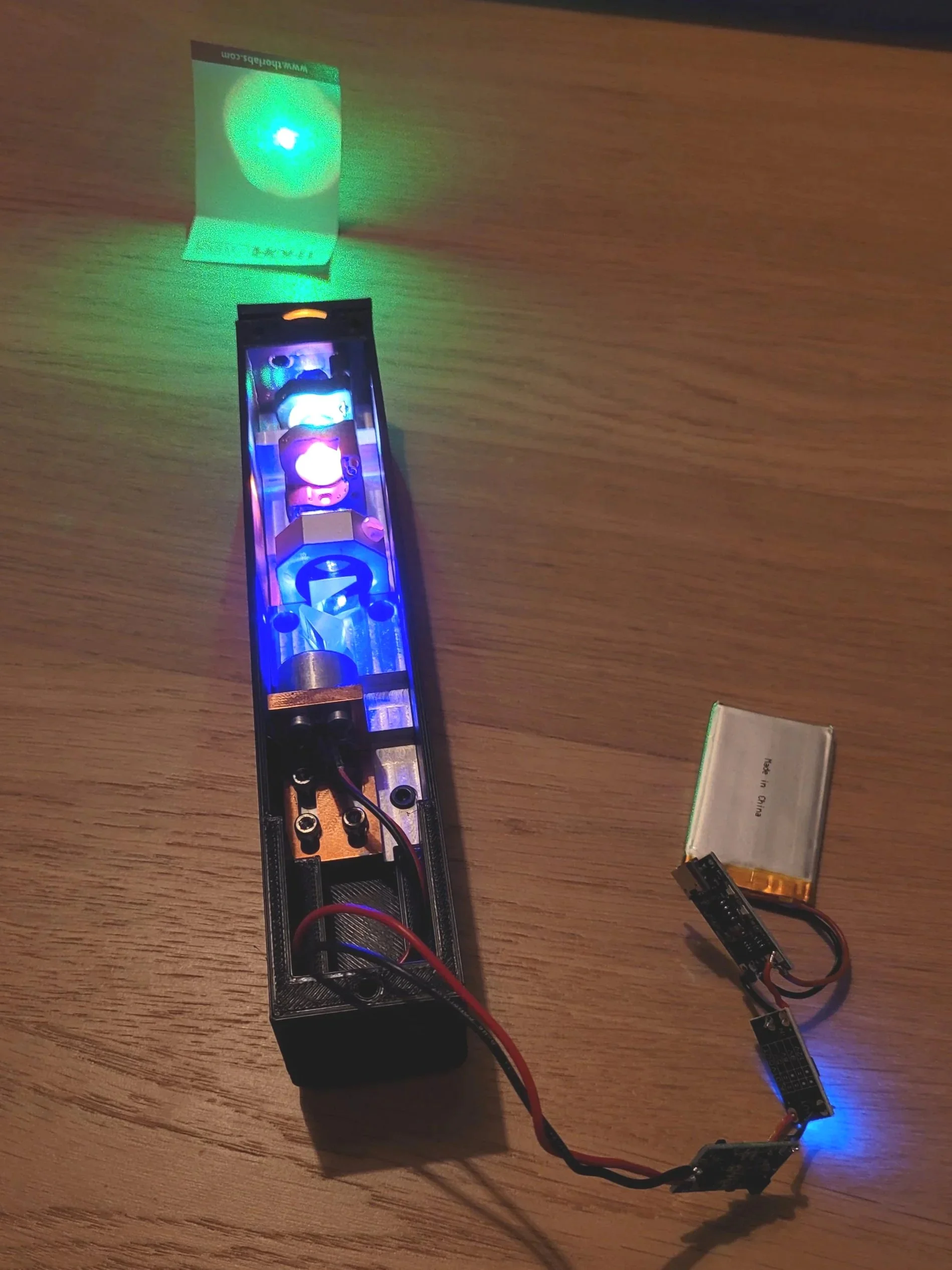
In this article I proudly present to you probably the most unusual laser pointer you have ever seen: An ultra-compact Pr:YLF laser emitting at 523 nm, pumped with a beam corrected blue laser diode. This fairly advanced laser system is so compact that it fits in a laser pointer sized housing (including laser driver and batteries!). The cavity alignment is robust enough that the laser can handled without special care.
Towards the end of the article I also show some higher order intracavity modes clearly visible mid-air, which is something I had never seen before.
The laser medium
In case you are not familiar with the wonderful Pr:YLF laser medium, I refer you to my previous article on a Pr:YLF laser emitting green, orange and red laser light. In summary, Praseodymium-doped Yttrium Lithium Fluoride, Pr:YLF, has several laser transitions in the visible spectrum (e.g. 523 nm, 604 nm and 640 nm), making it potentially interesting for the life sciences and display applications, where high brightness visible light is needed. It is also possible to frequency double these wavelengths into the UV, making potentially very efficient UV-lasers. What makes this laser medium particularly interesting for hobbyists though is that it can be pumped at 444 nm, which is exactly in the spectral regime where powerful and cheap InGaN laser diodes exist. In this project, I use an Osram PLTB450B laser diode to pump a laser cavity designed for 523 nm.
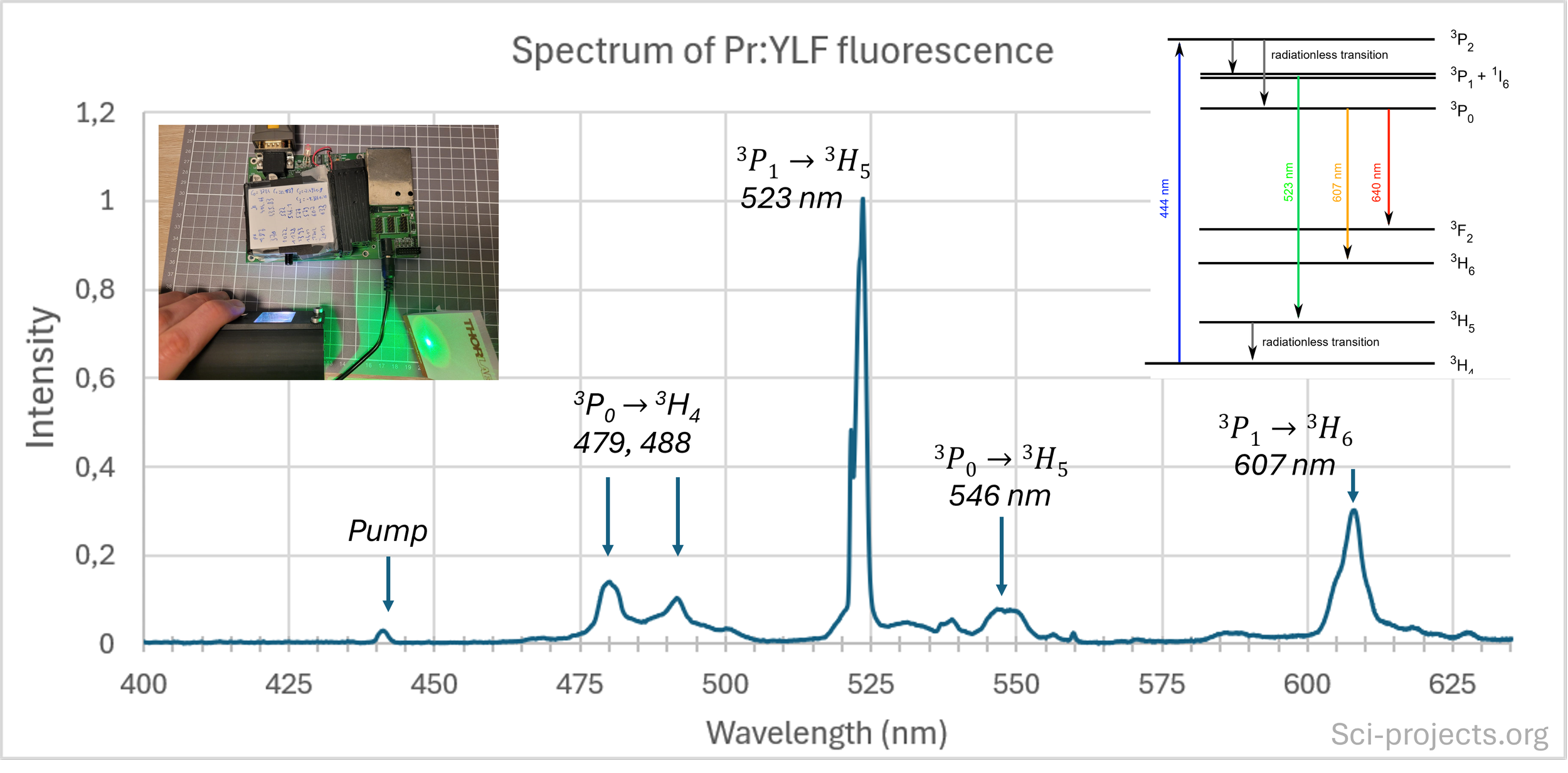
Spectrum of the pumped laser medium. The brilliant white is created by the blue pump and the spontaneous emission of the different transitions of the laser medium mixing together.
The laser design
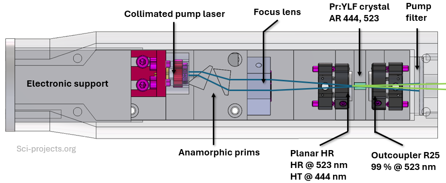
The design goal of this project was to create a fully self-contained laser system as compact as possible. In the picture below, I provide an overview over the electrical and optical architecture of the laser system.
The laser cavity
With every centimetre counting, the cavity is designed to be a hemispherical cavity with only 25 mm cavity length. This brings several big advantages: Since the hemispherical cavity is, optically speaking, a folded concentric cavity, it is intrinsically compact. Furtermore, it is easy to reach small pump spot sizes in the crystal, since the plane pump mirror does not distort the pump beam and is directly next to laser medium, allowing for short focal length pump lenses. Another particularly relevant advantage is that this resonator type is fairly robust against misalignment, especially with small cavity lengths. Once initially aligned, the laser can be misaligned and still lase at pretty high mode orders (see below!). The output coupler is set to be 1%, to reduce the laser treshold and pump requirements.
In this case, due to component availability, I use cavity optics coated for the 523 nm laser line - resulting in a very nice green output. (Comment: Usually, green laser light is achieved through frequency doubling a Nd:YAG laser. Here it is directly emitted!).
The pump laser setup
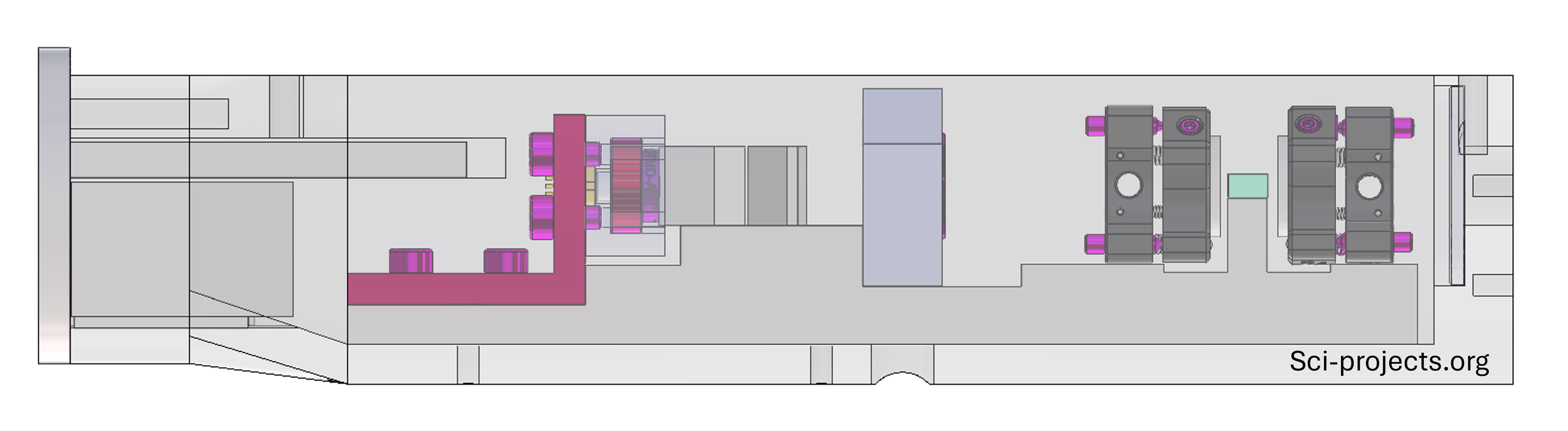
The pump laser diode (Osram PLTB450B) is mounted on a copper holder designed to give good thermal conductivity to the baseplate. It is first collimated using a high NA lens (Thorlabs C340TMD-A). To maximize the pump efficiency, the laser diode beam is corrected using an anamorphic prism pair. The idea here is that the anamorphic prism pair stretches the collimated oval laser beam emitted by the laser diode along one axis, in this case by about 6x, making it approximately round. This allows the focal spot to better match the optical mode in the laser resonator. Finally, the collimated and corrected beam is focussed into the crystal using a f=40 mm lens (Thorlabs LA1304-A). These 40mm bring a lot of extra undesirable length to the optical train, but are necessary for the following reason: A shorter focal length lens would decrease spot size in the laser medium, which initially sounds good, but it also decreases the rayleigh length of the pump, leading to a small length of the crystal being sufficiently pumped. In practice, this is a trade-off that depends on pump brightness, the laser medium itself, but also mode-matching between resonator and pump.
The electrical support system
The laser diode is supplied with a constant current from a compact laser diode driver (20×20mm), which itself is powered by a mini DC-DC step booster circuit, with the voltage coming from a small 3.7V 500mAh Lipo battery. The battery can be charged with a USB-C cable through a TP4056 charge circuit. Since this is very compact, it only lasts up to roughly 30 mins, which is very fine for a laser pointer.
Building and aligning the laser
I ordered the metal parts of the assembly from an online CNC-supplier, since I dont currently have access to my CNC. First, I collimated the laser diode by adjusting the collimator lens until the far-field over a few meters away was a similar size as the near-field beam. I then aligned the prisms according to their datasheet and glued them to the baseplate.
I first tested the cavity on an optical breadboard with adjustable stages for the OC and the pump focus lens, as you can see below.
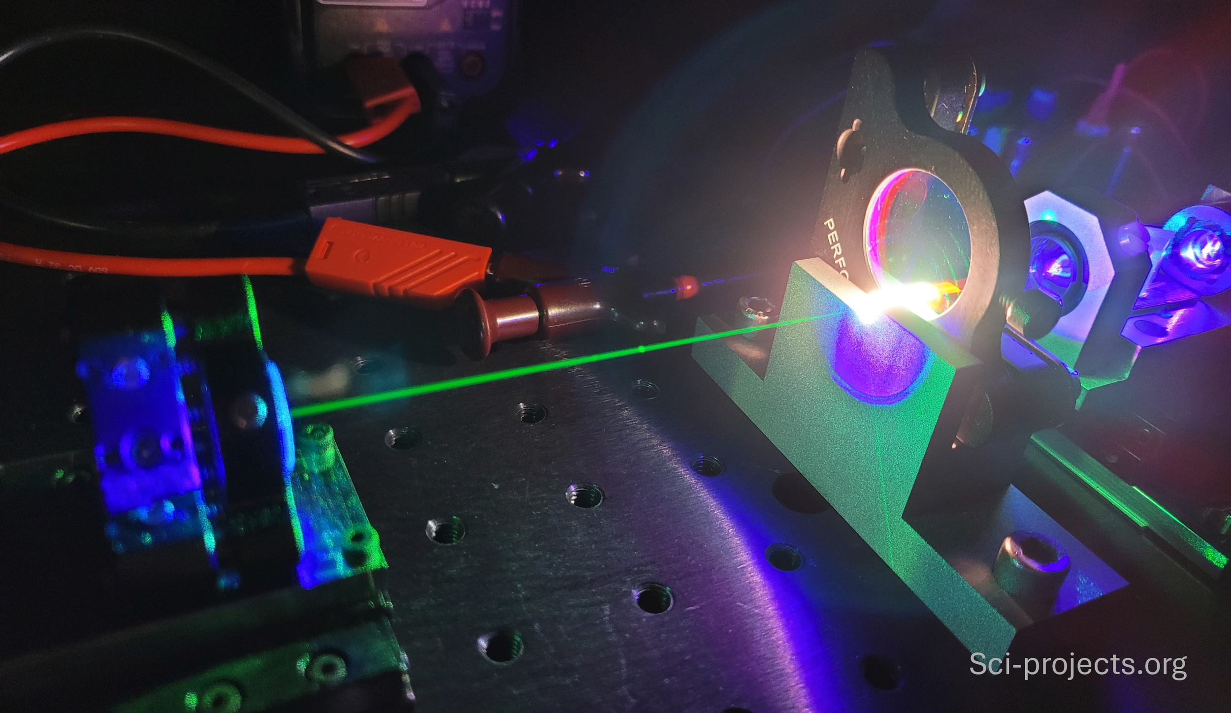
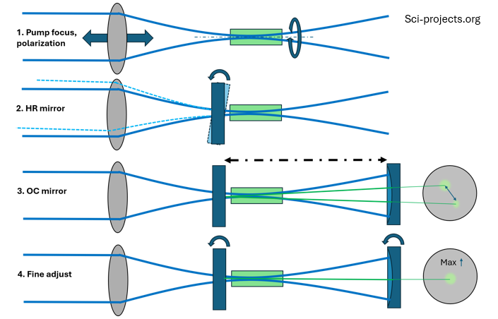
To get the system lasing initially, I first used a curved mirror with 0% transmission - less loss! This results in a cavity with very high intracavity powers, so you can see the beam inside the cavity easily (through rayleigh scattering). In case you are building a similar system, you may be interested in the alignment strategy:
The idea is to first set the pump focus roughly into the first 1/3 of the crystal, then rotate crystal to confirm the right polarization. At the right polarization, the crystal absorbs more, so the transmitted light is less. Then the HR is inserted and adjusted so that the back reflected pump light goes straight back into the pump. Since laser diodes can be sensitive to this, an AR coated HR mirror helps here - or you stop just shy of the laser diode facet. This sets the HR perpendicular to the optixal axis set by the pump. Then, the OC is inserted at the right position (measure with calipers and confirm with cavity stability simulation!). At this point you’ll see a) two stripes in the laser medium, the first from the pump and the second from the back-reflected pump and b) two fluorescent spots after the OC. To see b), you may need a pump filter. Adjust the OC so that the stripes and fluorescent spots align. Then you enter the fine aligment stage, in which you adjust the OC, HR and possibly lens focus / cavity length to achieve maximum fluorescence, and finally lasing. In my experience, adjusting the HR helps the most here, OC and pump tend to be pretty close already.
Once the components and designs were confirmed to be working, I transferred the components to the final baseplate and glued the crystal in place (after checking polarization!) using optical glue. This is important, never use normal superglue in direct vicinity to optics! It outgasses and hazes the pristine surfaces. With the mirror holders and crystals fixed, the only degree of freedom left is the focal spot position along the beam axis. Here, the lens holder is designed to allow for a few millimeters of longitudinal movement. Once the laser was aligned and working, I mounted the baseplate in the 3d-printed housing with a pump filter and the electronics.
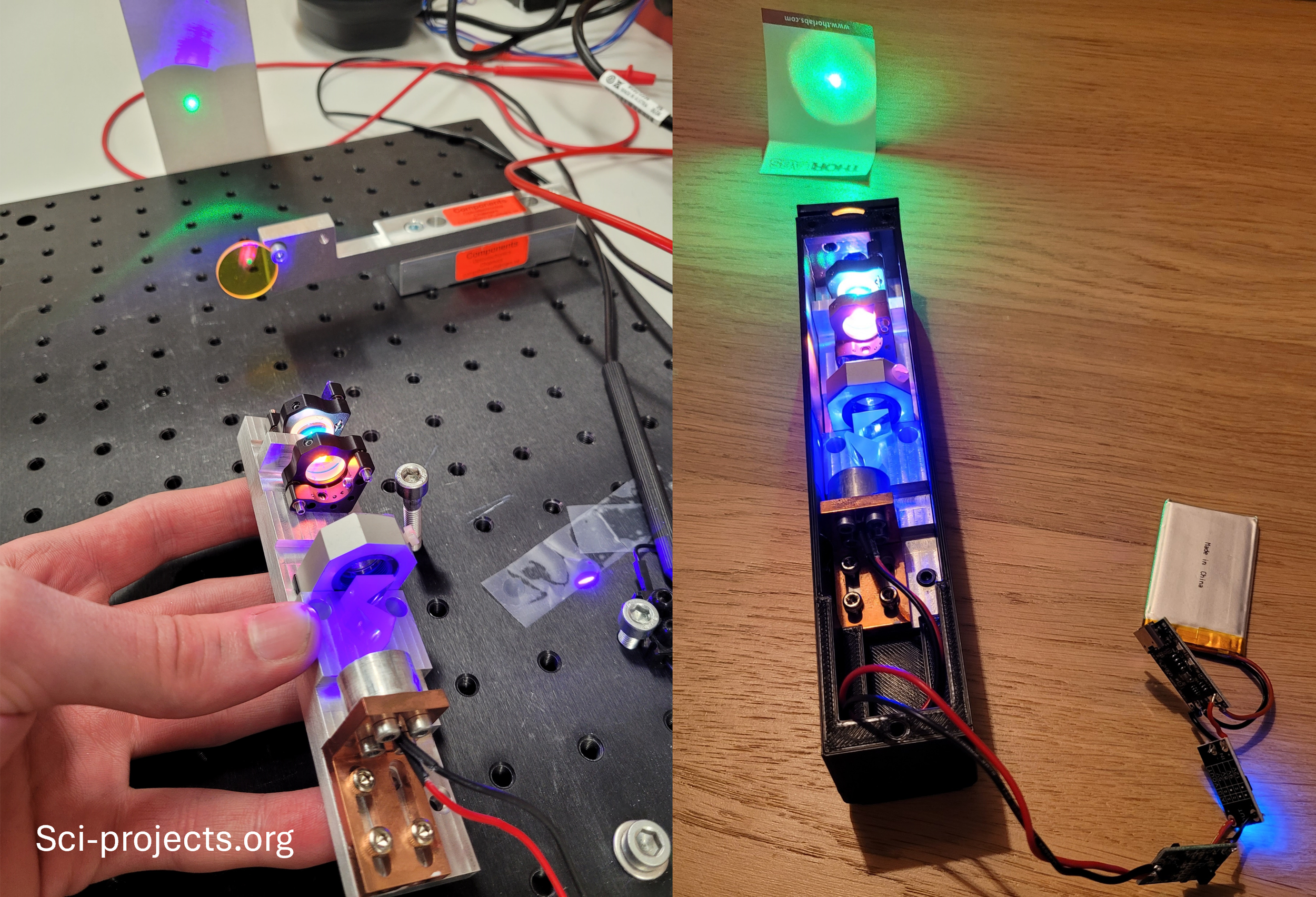
The pointer is then closed up with a lid which has a window, through which you can see the cavity and the fierce fluorescence of the crystal.
Of course I need to mention that this pointer is not intended to be used outside - it certainly is not a class 1 laser, though it would be easy to add an ND filter (and maybe a collimation lens) to the output end of the pointer and make it class 1.
This is the final pointer:
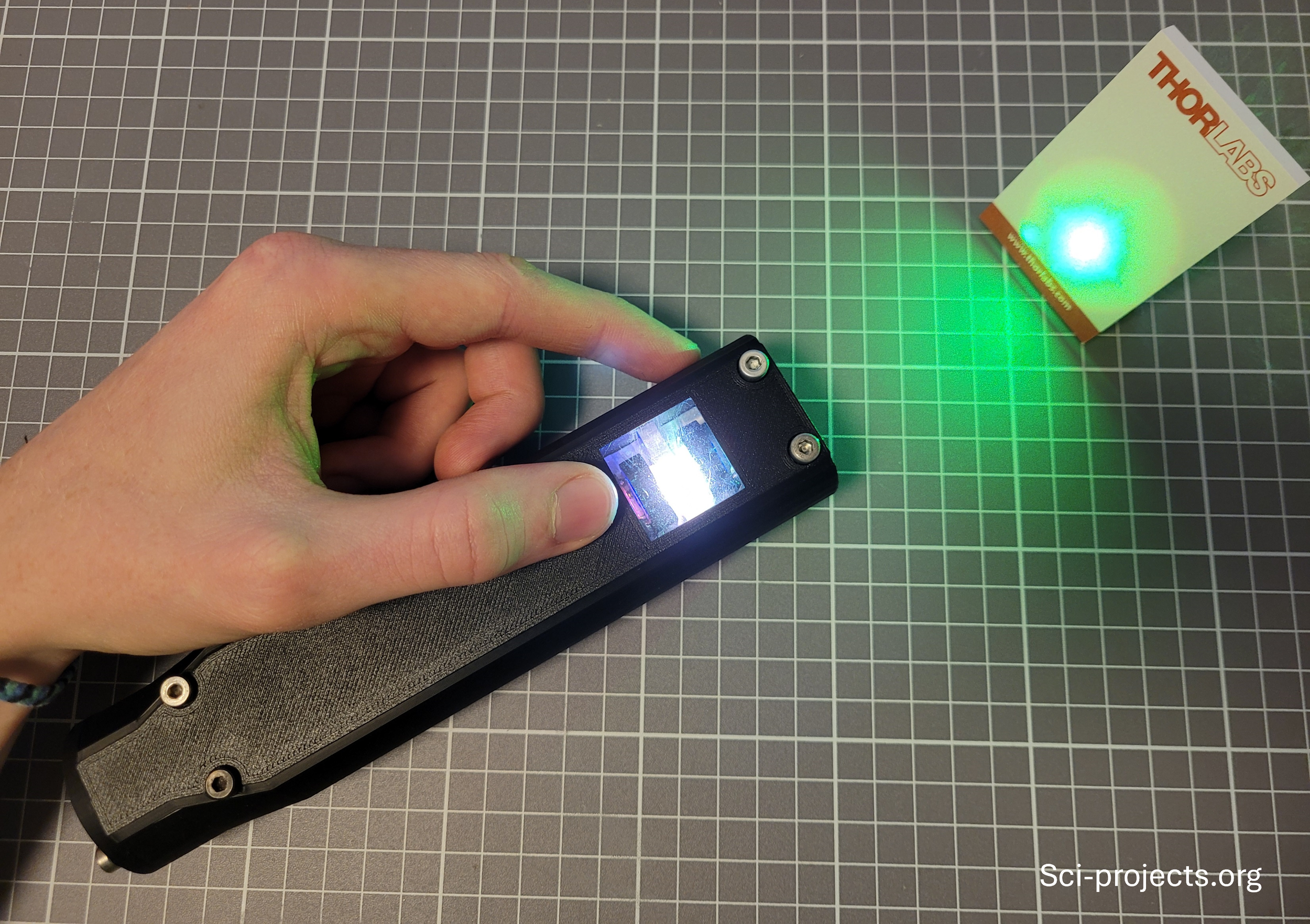
Interesting addition: Higher order modes!
The cavity is so tolerant against misalignment, that higher order modes are quite easy to attain. In case you are not familiar with this concept: The cavity modes are essentially intensity profiles that self-reproduce exactly after one roundtrip in the resonator and are thus stable. The simplest case is the round gaussian fundamental mode, but in some cases (e.g. misalignment), different patterns can actually experience higher gain in the cavity than this fundamental mode! The result of this can be quite interesting patterns:
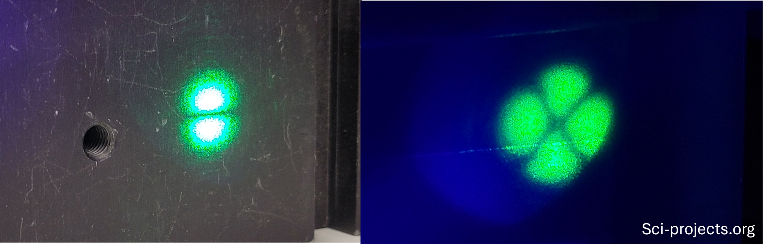
Something I had never seen before were HO-modes in free-space. You can see below what I mean. It is readily apparent how the beam is literally split, resulting in the patterns we see at the output. In this specific trial I was able to get up to the TEM05 mode, resulting in a 6-fold split of the intracavity beam. The reason why we can see the beams so clearly is the high power circulating in the cavity scattering at air molecules.
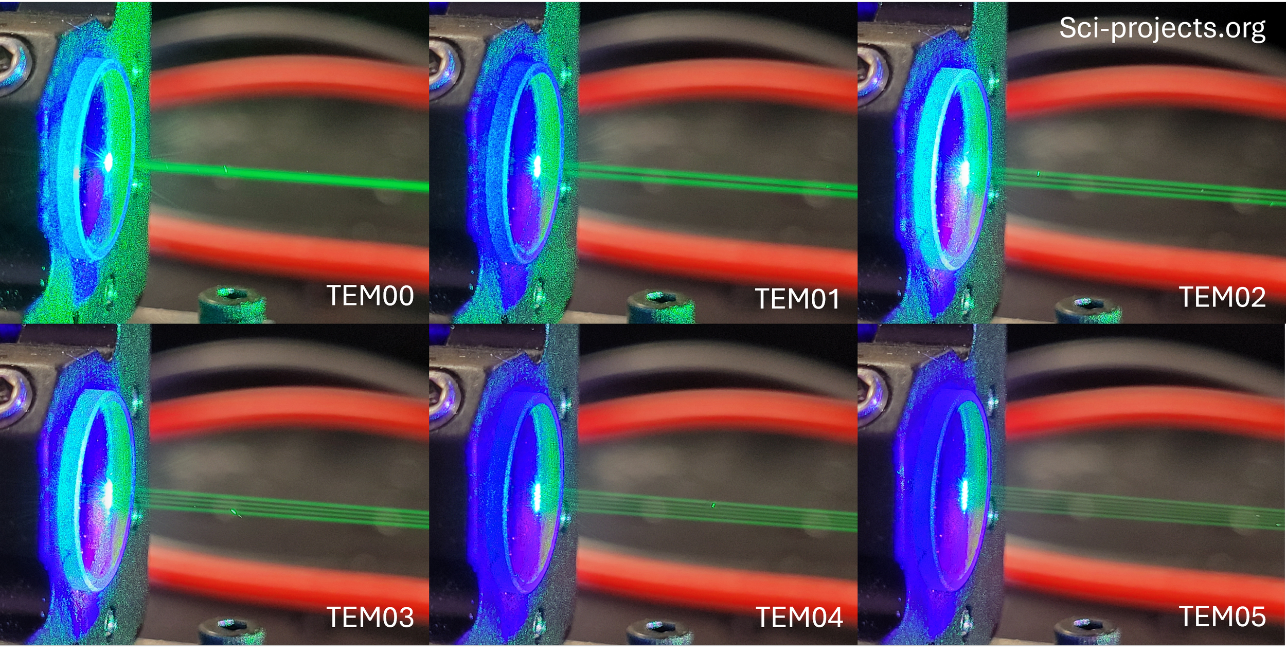
Below is a video of me tuning through the modes, finally reaching the fundamental TEM00 mode.
I hope that this short article was interesting for you! It was certainly a very fun project to build this unusual laser.
~N
PS: Thank you Michael and Alex for your significant contributions to the project! I appreciate it a lot.